This development blog post describes my workflow for creating organic models in virtual reality using Medium and then processing these models with a couple of tools for use and real-time display as optimized static meshes in the Unreal Engine.
In this tutorial I'll show how to create and paint a high resolution 3D model in Medium, export it to Blender to clean it, create a retopo mesh with MeshLab, then create a UV map and bake images in Blender, paint the model in Quixel Mixer and finally display the model in the real-time Unreal Engine. All the tools are available for free, except the optional UV islands packer.
Table of Contents
1. Tools
- Medium by Adobe ( aka Oculus Medium - latest version - free ) - Virtual reality voxel-based sculpting tool.
- Blender ( v 3.3.3. - free ) - Free and open source 3D creation suite.
- MeshLab ( latest version - free ) - Open source system for processing and editing 3D triangular meshes.
- UVPackMaster ( v 2+ ) - UV packing engine.
- Krita ( latest - free ) - Painting program.
- Quixel Mixer ( latest - free ) - Texturing made simple.
- Unreal Engine ( v 5 - free ) - Most powerful real-time 3D creation tool.
2. Medium
You can change the background color in the User Preferences.
Medium still has a very ugly paint brush bug. It mixes the lightness of soft brushes too dark. To fix this you can use the new Substance 3D Modeler.
2.1. References
 Place your reference images in 3D space to get the correct shape and color of the model you want to create.
You can also get a free low-polygon version of the model you want to create from websites like TurboSquid to get the proportions right.
2.2. Sculpting
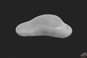
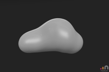
Create a rough skeleton of the model in the center of the layer.
Your model should fill about 1/4 of the layer's boundary cube.
Then fill in the gaps between the skeleton, creating a closed-surface object.
You don't need to be precise.
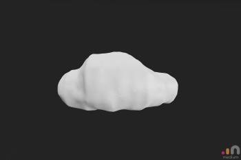
Now smooth ( fill ) the model with 100% strength.
The low layer resolution helps to speed up the process.
Then smooth ( average ) the model further.
You can change the roughness of the model in the settings and even set a lamp to better see the model's surface.
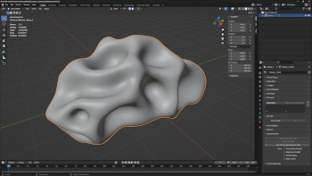
Export the smoothed model with 100% resolution as .FBX file to Blender to create a massiv object of the model that is not hollow.
In Blender select the object and switch to Edit Mode. Deselect all, then select one vertex.
Press the L key to select all connected vertices, invert the selection and delete all selected vertices. Switch back to Object Mode.
( If you want to change the proportions of the model use e.g. a Lattice modifier or a simple scale limited to one axis. )
Export the model as .FBX file and import the model to Medium as clay. Use the same resolution like you did for your original sculpt.
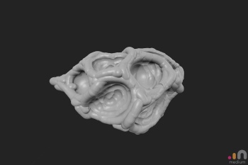
Back in Medium hide the original layer and sculpt the object's rough details on the new, imported layer.
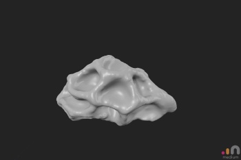
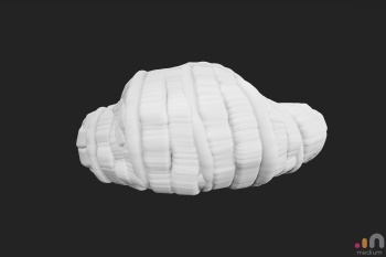
When you are done with the rough details smooth ( fill ) the model again.
Then smooth ( average ) the model further again.
For a final polish use the smooth tool at about 30% - 50% strength!

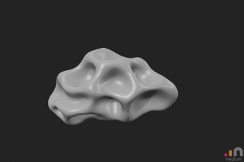
Finally set the layer resolution to 80% - 100% for very detailed painting and smooth color transitions. Make sure the edges of the model are not cut off by a too high layer resolution.
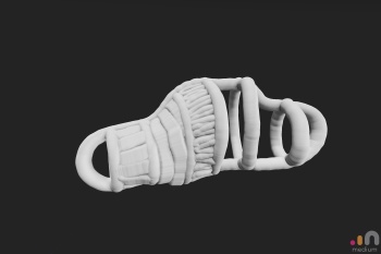
Paint the model with at least three different color layers to make it look interesting.
Export this final model with 100% resolution, vertex colors and as .FBX.
3. Blender
Blender can be extremely slow when you work with very high polygon models.
I recommend you to set the menu bar -> Edit -> Preferences... -> Keymap -> Preferences -> Spacebar Action to Search and
Properties Editor -> Scene Properties -> Units -> Unity System: Metric and Length: Centimeters
After you've finished this part of the tutorial you should save and then delete the models in the project file and save it as a blueprint for future projects. Then you have a lot of the setting you need to change in this tutorial as defaults.
3.1. Clean up
- Import your object as .FBX to Bender
- Set the pivot point ( surface )
- Snap the object to the scene origin
- Rotate it to the default starting position
- Scale the size to e.g. 5 m
- Apply all transforms
- Delete the not needed inner again ( remember the L key.. )
- Mesh -> Normals -> Select all vertices and Recalculate Outside
- Object Data Properies ->
- Geometry Data -> Clear all e.g. Custom Split Normals Data
- Attributes -> Clear all, except Vertex Colors
- Set Shade Smooth and disable Auto Smooth ( F9 )
- Smooth modifier -> Factor: 1; Repeat: 5 -> APPLY
- Export your model as .OBJ to automatically create a retopology of it in MeshLab
3.2. Retopology
- Import your mesh to MeshLab
- Remeshing, Simplification and Reconstruction -> Simplification: Quadric Edge Collapse Decimation -> Target number of faces: e.g. 3000
- Export mesh as .OBJ
- Import the .OBJ to your Blender project with the high resolution sculpt.
The low polygon model should be at the same location like the high poly model.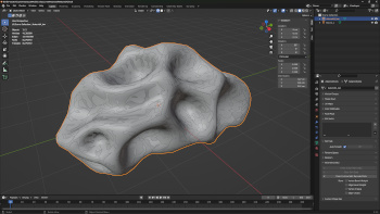
- Select -> Select All by Trait -> Interior Faces: Delete these faces
- Normals -> Recalculate Outside
- Object Data Properies ->
- Geometry Data -> Clear all e.g. Custom Split Normals Data
- Attributes -> Clear all
- Set Shade Smooth and disable Auto Smooth ( F9 )
- Manually clean the mesh from black spots and other really ugly topology
You can enable Object Properties -> Viewport Display -> In Front and
Snapping -> Face Project to move a select vertex with G key along the sculpt surface.
Click Alt + middle mouse button to navigate and hold middle mouse button to orbit. - Select -> Select All by Trait -> Non Manifold: To select all vertices that mark a hole in your mesh.
Close these holes.
3.3 UV Islands
- Hide the high poly sculpt and select the low poly retopo.
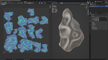
- Switch to UV Editing workspace to create a UV islands of your model's mesh.
- Keep the UV and Edit Mode selection in sync with UV Editor menu bar -> UV Sync Selection button ( arrow up & arrow down ).
- Mark edges as seams to create UV islands, the individual ( mesh ) pieces of a UV map. Mark the selected edges as seam with right click context menu -> Mark Seam in Edge Select Mode of the 3D Viewport. You can undo this by using the right-click context menu -> Clear Seam. ( You can also add these commands to the Quick Favorites. )
- To apply the seams to your UV map select all edges and then use 3D Viewport -> U key -> Unwrap with Method set to Angle Based and a Margin of about 0.005.
- To check the distortion of the UV islands enable menu bar of the UV Editor ( mouse wheel helps ;) ) -> Overlays button -> UV Editing -> Display Stretch -> Area
A blue to greenish hue means everything is fine to OK. Yellow ( or even red ) colors mean that the map is distorted ( or the relative scale is wrong ). Cut the mesh with seams until the UV islands are blue to greenish. I ended up with 14 islands for my model. Only a couple of islands are bad for the UV cover area and too many islands are bad for the performance. - You can further reduce the stretch with menu bar -> UV -> Minimize Stretch ( Enter ) -> Blend: 0 and Iterations 13. ( Press F9 if the context window doesn't show up. )
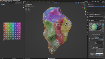
- Create a color grid image to check the final UV map for distortions.
- To see the grid image change the Viewport Shading ( Z ) in the 3D Viewport to Material Preview.
- Then Properties Editor -> Material tab -> New to create a new material that can display an image as texture. Click the small circle icon on the left side of the Base Color and select Texture -> Image Texture.
- + New to create a new image. Name it ColorGridCheck, Width & Height: 4096, disable the Alpha channel, select Color Grid as Generated Type and click OK.
3.4. UV Map
You can create a UV map of your UV islands manually or use a tool like UVPackmaster to do it automatically.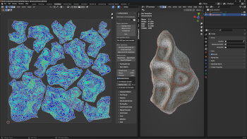
In this tutorial I use UVPackmaster 2 PRO. Get my settings here.
-If you do it manually: Good luck.
If you use UVPP make sure you run an Overlap Check and Validate UVs after selecting all faces of the model and before you Pack.
The final UV atlas should cover about 70% ( or even a little bit more ) of your UV map.
You can also add the UV islands of several objects to one UV map to create a UV atlas.
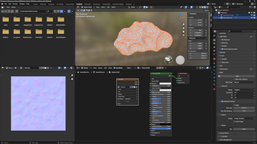
3.5. Bake Images
To bake the e.g. color data of the high resolution sculpt to an image to use it on your low poly retopo you need to change some general project settings in Blender.
- Properties Editor ->
- Render Properties ->
- Render Engine: Cycles
- Device: GPU Compute
- Sampling -> Render ->
- Noise Threshold: disabled
- Samples: 256
- Denoise: disabled
- Material Properties -> delete the material to display the color grid image to check the UV map for distortions and create a new one.
- Render Properties ->
Double check to bake with the high resolution sculpt model and the low resolution retopology model set to Smoooth Shading!
3.5.1. Normals
Bake the normals of the high resolution sculpt to an image to display a smooth surface on the low poly retopo.
- Switch to the Shading workspace!
- Properties Editor -> Render Properties -> Bake ->
- Bake Type -> Normal
- Influence -> Swizzle -> G -> -Y ( Blender uses OpenGL ( +Y ) but you need a DirectX normal image for Unreal. )
- Selected To Active ->
- Enabled
- Extrusion -> Calculate the extrusion with the formula: extrusion = ( longest model side + shortest model side ) / 200
For example: ( 552 cm + 296 cm ) / 200 = 4.24 cm extrusion
If you notice yellow spots in very narrow places of the model on your normal image you can try to divide the extrusion value by 2.
- Output -> Clear Image: enabled
- Margian -> Size: 16 px
- In the Shader Editor menu bar -> Add -> Texture -> Image Texture node and select it without to connect it.
- On the Image Texture node create a + New image with
- Name: Normals
- Width & Height: 4096
- Alpha: disabled
- Generated Type: Blank
- 32-bit Float: enabled
- Set the Color Space on the Image Texture node to Non-Color.
- To see the baked image switch to the Normals image in the Image Editor on the left side.
- Make sure both, the high and low poly models, are visible / enabled in the Outliner for both the Viewport and Renders view. ( eye and camera symbols )
- Select the sculpt model and then CTRL + select the low poly model to multi select both in this particular order.
- Properties Editor -> Render Properties -> Bake -> Bake button to finally bake the normals to the image.
- To save the image click the three horizontal lines button in the Image Editor menu bar -> Image -> Save As...
- as .PNG
- Color: RGB
- Color Depth: 16
- Compression: 100%
- Color Space: Non-Color
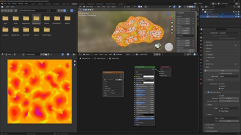
3.5.2. Ambient Occlusion
To bake the darkness in e.g. narrow corners of your model change the following settings in the Shading workspace.
- Properties Editor -> Render Properties ->
- Light Paths -> Fast GI Approximation: enabled
- AO Distance: 10% of max. model size
In my example the max. length is 552 cm so the AO distance is 55.2 cm.
- AO Distance: 10% of max. model size
- Bake ->
- Bake Type -> Ambient Occlusion
- Output -> Clear Image: disabled
- Margian -> Type: Extend
- Light Paths -> Fast GI Approximation: enabled
- On the Image Texture node create a new image with the two papers button.
- Name: AmbientOcclusion
- Width & Height: 4096
- Color: White
- Alpha: disabled
- Generated Type: Blank
- 32-bit Float: disabled
- Name: AmbientOcclusion
- Set the Color Space on the Image Texture node to Non-Color.
- With the Image Texture node selected Properties Editor -> Render Properties -> Bake -> Bake button
- To save the image click the three horizontal lines button in the Image Editor menu bar -> Image -> Save As...
- as .PNG
- Color: RGB
- Color Depth: 8
- Compression: 100%
- Color Space: Non-Color
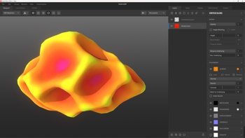
- Open the saved ambient occlusion image in Krita to create a smoother shading.
- menu bar -> Filter -> Blur -> Blur
- Overwrite the original AmbientOcclusion.PNG file to save the smoothed image.
3.5.3. Vertex Colors
To bake the painted ( vertex ) colors of your model change the following settings in the Shading workspace.
- Select the high resolution sculpt.
- Create a + New material in the Shader Editor.
- Add -> Input -> Color Attribute node
- Connect the Color pin of the Color Attribute node to the Base Color pin of the Principled BSDF node to display the vertex colors.
- Select the sculpt model and then CTRL + select the low poly model to multi select both in this particular order.
- Properties Editor -> Render Properties ->
- Bake ->
- Bake Type -> Diffuse
- Output -> Clear Image: disabled
- Margian -> Type: Extend
- Influence -> Contributions ->
- Direct: off
- Indirect: off
- Color: on
- Bake ->
- On the Image Texture node create a new image with the two papers button.
- Name: VertexColors
- Width & Height: 4096
- Color: Choose the most dominant vertex color and where the most seams are located of the high resolution model. I chose a yellow - orange color.
- Alpha: disabled
- Generated Type: Blank
- 32-bit Float: disabled
- Name: VertexColors
- Set the Color Space on the Image Texture node to sRGB.
- To see the baked image switch to the VertexColors image in the Image Editor on the left side.
- To save the image click the three horizontal lines button in the Image Editor menu bar -> Image -> Save As...
- as .PNG
- Color: RGB
- Color Depth: 8
- Compression: 100%
- Color Space: sRGB
3.6. Export
Select the low poly retopo model in Object Mode and then create an Operator Preset that can be reused and is compatible with Unreal Engine:
Main menu bar -> File -> Export -> FBX (.fbx)
- In the Blender File View window change the settings Include ->
- Enable Limit to Selected Objects
- Only enable Mesh in Object Types to export.
- Transfrom ->
- Forward -> X Forward
- Up -> Z Up
- Geometry -> Smoothing -> Face
Create the Operator Preset with the + button at the top right of the window, then name the low poly model and Export FBX.
4. Mixer
In this tutorial for this very simple model I use Mixer only to combine the baked ambient occlusion with the baked vertex colors and export it as a "diffuse" image.
Set the lighting to Flourescent.
- Create a new Mix with a resolution of 4096.
- Setup tab ->
- Model Settings -> Type: Custom Model
- Texture Settings -> Edit Texture Sets ->
- Base Maps -> Normals ->
- Load your Normals.PNG
- Invert Normals Y: Enabled ( Mixer uses a Unity renderer that uses OpenGL instead of DirectX like Unreal. )
- Close
- Base Maps -> Normals ->
- Layers tab ->
- Add two Solid Layers.
- Name the upper layer AmbientOcclusion and the lower layer VertexColors.
- VertexColors layer ->
- Placement -> Tiling
- Albedo -> Load -> VertexColors.PNG
- AmbientOcclusion layer ->
- Blend -> Opacity: 0.5
- Placement -> Tiling
- Albedo ->
- Load -> AmbientOcclusion.PNG
- Set the blend mode from Normal to Multiply
- Export tab ->
- Export Target ->
- Set an Export Location
- Disable Create Subfolder
- Textures -> Texture Maps -> Only enable the Albedo channel.
- Export Target ->
- Export To Disk.
5. Unreal
5.1. Import
- Open the Content Drawer of the Unreal Engine Editor with CTRL + Spacebar.
- Navigate to or create a Models folder.
- Content Drawer -> menu bar -> + Add -> Import to /Models
- For this simple model, that targets PC as well as Mobile platforms, I change these default settings:
- Mesh ->
- Generate Missing Collision: Disabled
- Advanced -> Generate Lightmap UVs: Disabled
- Material ->
- Material Import Method: Do Not Create Material
- Import Textures: Disabled
- Mesh ->
- Navigate to or create a Textures ( Image Textures if you want to be more precise.. ) folder.
- Content Drawer -> menu bar -> + Add -> Import to /Textures
- Multiselect the Color/Albedo and Normals image and open them.
- Navigate to or create a Materials folder.
- Content Drawer -> menu bar -> + Add -> Material
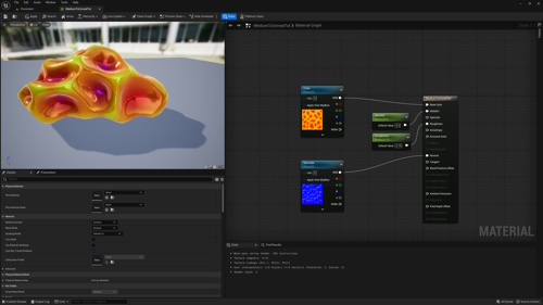
- Open the Material and add two TextureSample nodes with right click. Right click each and Convert to Parameter and name one Color and the other Normals.
- Set the Normals TextureSample node to Details -> Material Expression Texture Base -> Sampler Type: Normal
- Connect the Color node's RGB pin to the Base Color pin and the Normals node's RGB pin to the Normal pin.
- Add two Constant nodes, Convert to Parameter and use them to control the Metallic and Roughness.
- Navigate to the model in the Content Drawer and open the model in the Static Mesh Editor with right click -> Edit...
- Set your material as the Details window -> Element 0 Material Slots material.
5.2. Level of Detail
To automatically create lower resolution versions of your model in the Static Mesh Editor, simply set the Details window -> LOD Settings -> Number of LODs: to e.g. 3 and Apply Changes.
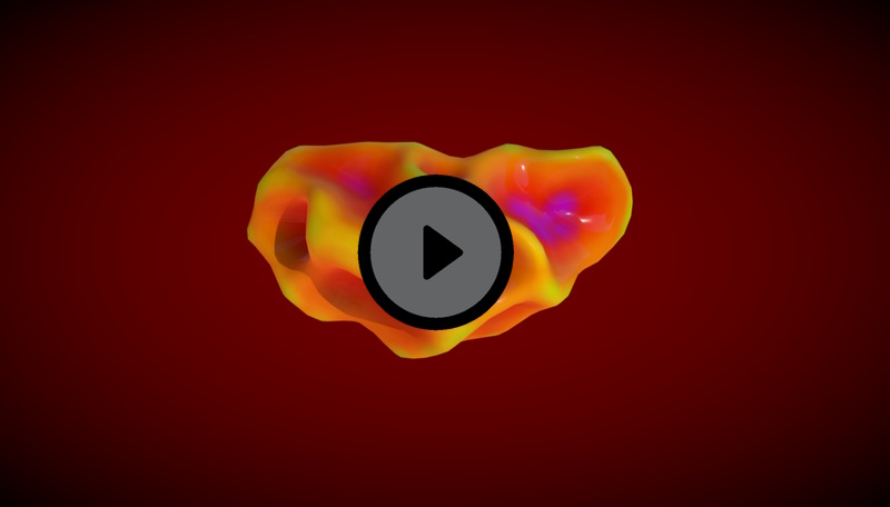
6. Real Time Demo
View the final 3D model on SketchFab.